
10
Jun
Abstract
The International Telecommunication Union (ITU) Radiocommunication Working Party (WP) 4C met from 22nd April to 1st May 2026 in Geneva. It addressed a wide range of topics related to more efficient use of the orbit/spectrum resources by the mobile satellite service (MSS) and the radiodetermination-satellite service (RDSS) systems. Several World Radiocommunication Conference 2027 (WRC-27) agenda items (AIs) relate to provision of direct to device (D2D) services from orbit, in particular AIs 1.13 and 1.14. After nearly two weeks of intense discussion, the current state of the work was document in the WP 4C outputs or TEMPs. This paper shows how information in these WP 4C TEMPs can assist in modelling D2D systems in detail using the Visualyse Professional tool.
WP 4C Output TEMPs
The output of ITU-R WP 4C was a series of TEMPs documents, either liaison statements to other groups or documents to be attached to the Chair’s Report for further consideration at the next meeting. This paper focusses on one of these outputs, namely 4C/TEMP/170 and associated parts on the topic of “Working Document on Sharing and Compatibility Studies under WRC-27 AI 1.13”. According to WRC-23 Resolution 813, this AI is to:
1.13 to consider studies on possible new allocations to the mobile-satellite service for direct connectivity between space stations and International Mobile Telecommunications (IMT) user equipment to complement terrestrial IMT network coverage, in accordance with Resolution 253 (WRC-23);
It should be noted that TEMP/170 clearly identifies that the contents:
have not been adequately discussed in detail and are not agreed and will need to be carefully examined and possibly updated depending on comments, agreed parameters and information on updates to the relevant modelling.
However, it describes a number of useful concepts, in particular ideas on how to model D2D satellite systems, including:
- Non-GSO MSS gain patterns
- Satellite and antenna orientation
- Satellite beam management mechanisms
- Satellite transmit power control methods
- Tracking strategies and satellite selection.
Other TEMPs cover other related topics and are worth further reading. In particular:
- 4C/TEMP/172 contains a working document towards a preliminary draft new Recommendation (PDNR) of gain patterns to use for non-GSO MSS systems
- 4C/TEMP/173 describe system architectures and give more information on beam management techniques.
This paper discusses some of the engineering techniques proposed for non-GSO D2D systems and how they can be modelled in Visualyse Professional.
Note that these documents, when attached to the WP 4C Chair’s Report, are assigned different references. For example:
- 4C/TEMP/170 became 4C/744/Annex 10
- 4C/TEMP/172 became 4C/744/Annex 25
- 4C/TEMP/173 became 4C/744/Annex 11.
Motivations for Detailed Modelling
The results of simulation are only as accurate as the inputs and modelling methodologies involved. Non-GSO D2D systems such as SpaceX’s Starlink and AST Mobile’s constellation are proposing to use a range of advanced engineering solutions including phased array antennas, power control, satellite orientation control, tracking strategies, interference management techniques and adaptive modulation and coding (ACM). These factors have a significant impact on the resulting interference levels, and models that over-simplify can lead to inaccurate results and misleading conclusions.
While many of these techniques are currently being discussed within ITU-R WP 4C as part of the development of D2D sharing methodologies, they are not entirely new concepts. Transfinite Systems has been actively involved in non-GSO sharing studies for more than three decades, and many of the modelling approaches now being considered have their origins in earlier generations of non-GSO systems. Visualyse Professional has historically evolved alongside the ITU regulatory process, often incorporating capabilities needed for emerging studies before formal methodologies were fully established. As a result, many of the concepts currently under discussion within WP 4C can already be represented directly within Visualyse Professional today.
This is important for a range of studies including:
- System design: when developing a non-GSO D2D system, to analyse the capacity, throughput and coverage in detail, taking into account constraints such as intra-system interference
- Interference analysis: when undertaking studies of sharing between non-GSO D2D systems and other non-GSO MSS constellations, terrestrial IMT deployments and other services such as programme making and special events (PMSE)
- Regulation and licensing: such as developing power flux density (PFD) limits as part of a possible Method to address AI 1.13 at WRC-27 or during licensing by ensuring that a non-GSO D2D system meets them.
These studies require detailed and accurate models for the results to be useful, particularly important as WRC-27 gets ever closer and the need for well-reasoned and evidence supported solutions becomes acute.
The following sections identify key elements from the WP 4C TEMPs and demonstrate how these D2D constellation engineering techniques can be represented within Visualyse Professional. In many cases these capabilities are already available within the software, reflecting Visualyse Professional's long-standing development alongside evolving ITU-R study methodologies..
Modelling non-GSO D2D Systems
The interference environment created by a D2D constellation is determined not only by its orbital configuration and antenna characteristics, but also by the way the system operates. Modern D2D networks increasingly employ adaptive techniques including beam steering, power control, satellite selection and dynamic resource allocation. These mechanisms influence both the desired signal and the aggregate interference environment and are therefore becoming an important focus of current WP 4C studies.
A key objective of the proposed modelling approach is not simply to reproduce a single reference system, but to investigate how alternative operational assumptions influence sharing outcomes. Visualyse Professional provides the flexibility to represent these behaviours explicitly, allowing sensitivity analyses to be performed as assumptions evolve within the ITU-R process.
A key source for this section was 4C/TEMP/170 Part 1, which is a “Working document on technical and operational characteristics of MSS for direct communication with IMT user equipment”. It discusses a number of different reference non-GSO MSS systems, where, for example:
- System 3 has two configurations with satellites at heights of either 525 km or 340 km. This is usually considered to be based upon SpaceX’s Starlink system
- System 4 has a number of satellite heights between 520 and 690 km and is usually considered to be based upon AST Mobile’s system.
There is also an associated spreadsheet with information about gain patterns, power per beam and PFD on the ground.
Satellite Gain Patterns
The non-GSO D2D systems are proposing to use phased array antennas at the satellite, and a key question is how these should be modelled in a detailed simulation. A number of gain patterns are referenced in 4C/TEMP/170, including:
- Recommendation ITU-R S.1528 Recommends 1.1 or 1.2
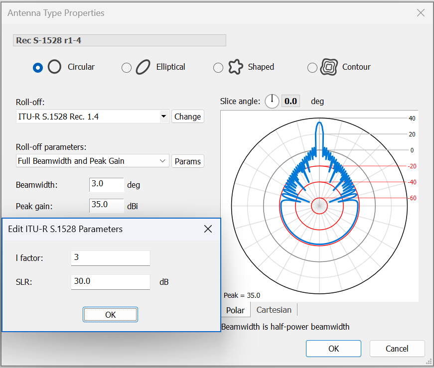
- Recommendation ITU-R S.1528 Recommends 1.4
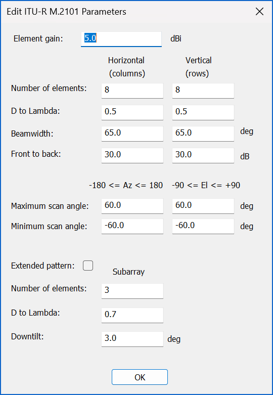
- Recommendation ITU-R M.2101
- Working Document towards a PDNR [MSS_SAT_ANTENNA_PATTERN] in 4C/TEMP/172 (currently the same as Recommendation ITU-R S.1528).
All of these are available in Visualyse Professional. Note that the implementation of Rec. ITU-R S.1528 recommends 1.4 includes the corrections in document WP 4A/927 and can be configured with the l-factor and SLR as shown in the figure below:
Similarly, the gain pattern in Rec. ITU-R M.2101 can be configured using the dialog below:
Satellite and Antenna Orientation
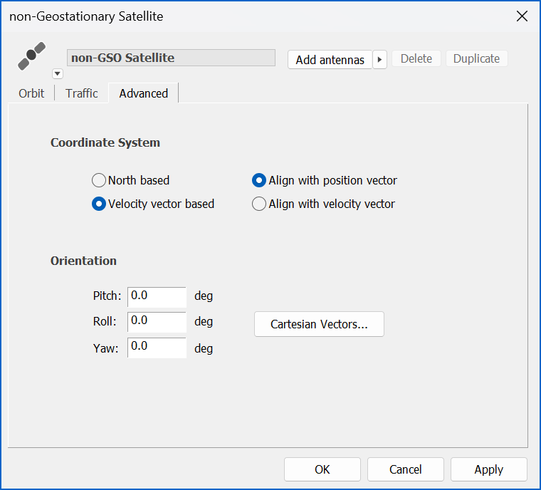
By default, the satellite is assumed to be orientated such that the phased array antenna physical boresight is pointing towards the sub-satellite point. However, 4C/TEMP/170 Part 1 suggests that in “exceptional” circumstances the satellite’s orientation can be modified by rotation in roll, pitch or yaw. This can be modelled in Visualyse Professional in one of two ways:
1. Direct control of the satellite’s roll, pitch, yaw angles as in the figure below:
2. By having the satellite antenna physically pointed at a target boresight position (e.g. latitude and longitude) and then steering its beams at the D2D UEs. This can be done by:
a) Configuring the D2D satellite’s Antenna pointing method to be controlled by the Link and have its Beams using electronically steering
b) Having a control Link from a boresight Station to point the satellite Antenna towards it
c) Having a communication Link that starts at the satellite and Antenna used by control Link and ends at the D2D UE, and which uses an electronically steered beam from within the Antenna pointed at the D2D UE.
Satellite Beam Management
One question to be considered when modelling the beams generated by the phased array antennas at the non-GSO D2D satellite is how the gain pattern changes as the beam is steered away from the physical boresight, typically the sub-satellite point (but not aways, as discussed above).
A number of methods could be considered as discussed in 4C/TEMP/170 and associated parts. The simplest is to keep the peak gain and beamwidth constant as the beam is steered, for example using the Rec. ITU-R S.1528 recommends 1.4 pattern as discussed above.
Use of the Rec. ITU-R M.2101 gain pattern results in the peak gain and beamwidth changing as the beam is steered as in the figure below.

Another method is described in 4C/TEMP/173, in which the beam is adjusted based upon the geometry so that the footprint on the ground is cell that remains fixed as the satellite moves. This can be achieved by creating a beam with cross section that is elliptical in the satellite’s reference frame such that the footprint approximates to circular on the ground. This implies wide circular beams sub-satellite and narrower more elliptical beams as it is steered towards the horizon, which suggests that the peak gain is also changed, increasing as the beam becomes narrower.
This can be modelled in Visualyse Professional using the footprint diameter option, as shown in the figure below:
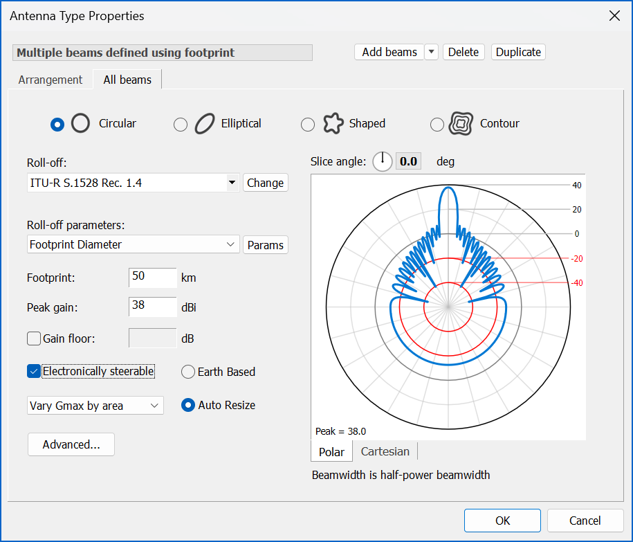
Note how this Antenna has been modelled as having multiple beams, each of which can be steered independently, reflecting typically D2D operations.
Satellite Transmit Power Management
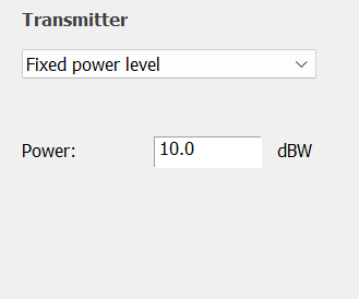
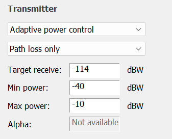
To undertake interference analysis, it is important to have an accurate model of the transmitter and the power emitted. For non-GSO D2D systems, there are a number of options as listed in 4C/TEMP/170 part 1:
In terms of modelling the variation of PFD with slant path, several options can be considered, and correspond to several ways operations can occur:
- Keep PFD constant on the ground, i.e. adjust eirp at the satellite to ensure a constant PFD on the ground regardless of the slant path / arrival angle
- Keep eirp constant at the satellite: this implies that the PFD value contained in Table 1 is only ensured at Nadir, while it will be lower at lower elevation, i.e. as the slant path increases
- Hybrid mode: some systems adjust the eirp to ensure constant PFD on the ground only up to a certain elevation angle, after which the eirp is not increased more, thus the PFD decreases as the elevation angle decreases
In addition, 4C/TEMP/170 Part 2 included a power control method aimed at keeping the link’s C/N constant. With a given noise temperature or noise figure, this is the same as a power control method with target receive C.
All these options can be modelled using Visualyse Professional with the power control features as shown in the figures below:
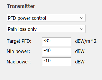
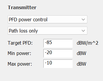
Note that the PFD power control algorithm can be used to set the PFD at the centre of the cell / beam, and then if the D2D UE is located elsewhere within the cell it could receive a lower PFD, taking into account the relative gain at the satellite.
Tracking Strategies
A key factor in any non-GSO D2D model is the tracking strategy, which is how the non-GSO satellite to serve a specific UE is chosen.
A number of factors are considered in document 4C/TEMP/170 part 1, including:
- Prioritize placing beams with the lowest scan angle / path length
- Distribute the beam count evenly among eligible satellites over the service area - Equal loading;
- The simulation/service area can be divided into cells and for each cell a beam is assigned to it from one of the eligible satellites.
- When a beam is placed right before the border or in its vicinity, select, among available satellites, those flying above the country where the D2C service is being provided.
These factors can be included in Visualyse Professional Tracking Strategies that take account of:
- Filtering by elevation angle
- Filtering by angle to a reference vector.
An example of the reference vector method is shown in the figure below.
Interaction of Operational Assumptions
Modern D2D systems rarely employ these techniques in isolation. Beam steering, power control, satellite selection and antenna orientation are often coupled through network optimisation algorithms. Consequently, compatibility studies may need to evaluate combinations of assumptions rather than individual mechanisms in isolation.
Visualyse Professional allows these interactions to be represented within a common simulation environment, supporting both deterministic and statistical analyses as required.
The techniques currently being discussed within WP 4C should not be viewed as independent modelling features but as components of an overall D2D system architecture. The flexibility to represent alternative assumptions, and to evaluate their influence on sharing outcomes, is likely to become increasingly important as international regulatory methodologies continue to mature.
Visualyse Professional provides a common modelling framework capable of supporting both current WP 4C studies and future developments as they emerge.
Example Simulations
The figure below shows an example simulation that takes account of the following parameters taken from 4C/TEMP/170, in particular the embedded spreadsheet:
| Parameter | Value |
|---|---|
| Constellation parameters | From USASAT-NGSO-20 |
| Direction | Downlink |
| Frequency (GHz) | 2.15 |
| Bandwidth (MHz) | 5 |
| Target PFD (dBW/m^2/MHz) | -90.4 |
| Satellite gain pattern | Rec. ITU-R S.1528 R1.4 (*) |
| Sub-satellite gain (dBi) | 41 |
| Maximum gain (dBi) | 46 |
| Beamwidth (deg) | 0.75 |
| UE gain (dBi) | -4 |
| UE noise figure (dB) | 9 |
| Cell deployment model | 19 cells in hexagonal pattern |
| Cell edge relative gain (dB) | -4 |
| Cell edge beamwidth (deg) | 0.87 |
| Cell diameter at 3 dB (deg) | 18.1 |
| Cell radius (km) | 10.4 |
| Inter-cell spacing (km) | 18.1 |
Note (*) this is a modification from the tables which suggest use of Rec. ITU-R S.1528 Recommends 1.1 or 1.2.
The scenario compares the results assuming two sets of features from those described in the previous sections:
Baseline:
- Gain pattern set to Rec. ITU-R S.1528 recommends 1.4
- Beam managed so that there is a constant footprint with peak gain that changes to adjust for differences in path loss
- Transmit power control to keep PFD at the centre of the beam constant as it is steered
- Selection of non-GSO satellite using highest elevation tracking strategy.
Variation:
- Gain pattern set to M.2101 with parameters to give a peak gain of 46 dBi when pointed towards sub-satellite point
- Fixed transmit power of 3 dBW
- Selection of non-GSO satellite using tracking strategy of random from those satellites above an elevation angle of 30
The scenario also includes an IMT cell operating in TDD mode in the adjacent channel and analyses non-co-frequency interference with the following parameters:
| Parameter | Value |
|---|---|
| Frequency (GHz) | 2.15 |
| Bandwidth (MHz) | 5 |
| IMT mode | TDD |
| BS gain pattern | Rec. ITU-R F.1336 |
| BS peak gain (dBi) | 18 |
| Horizontal beamwidth (deg) | 120 |
| Vertical beamwidth (deg) | 10 |
| Downtilt (deg) | 5 |
| UE gain pattern | Isotropic |
| UE gain (dBi) | -4 |
| UE noise figure (dB) | 9 |
| BS noise figure (dB) | 9 |
| Deployment model | hexagon |
| Hexagon radius (m) | 250 |
The adjacent channel interference ratio (ACIR) was assumed to be 25 dB. The simulations were run for a week’s elapsed time with time step of 5 seconds.
The resulting simulation is shown in the screenshot below.
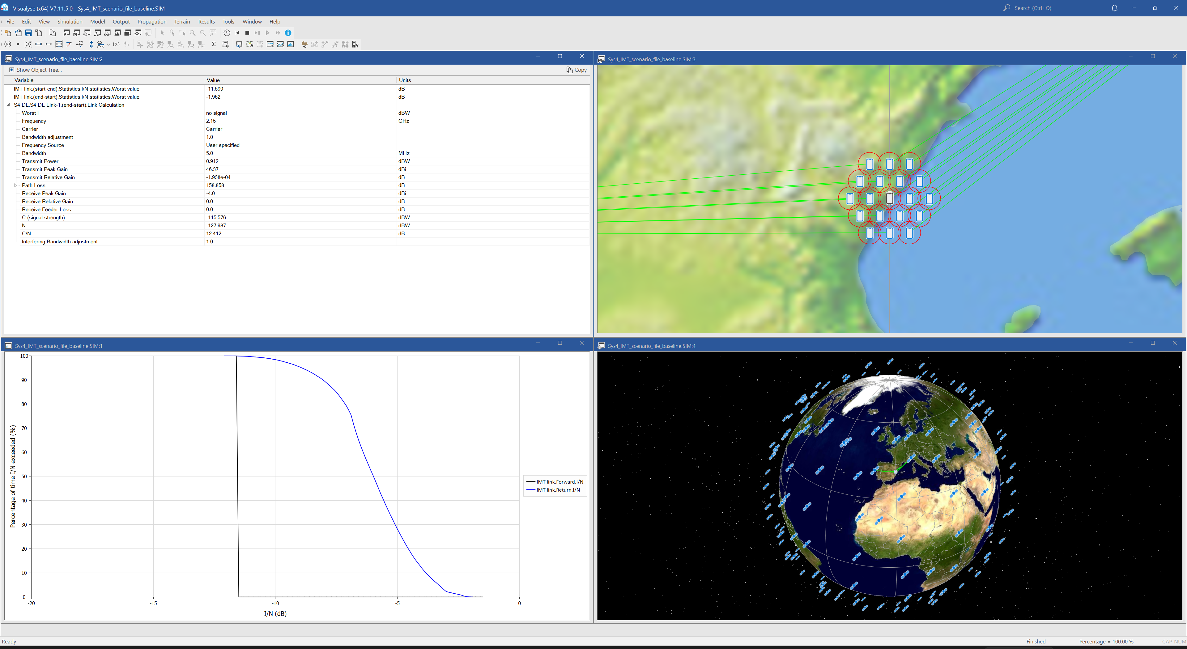
The results are different in two key aspects:
- The distributions of I/N from the D2D constellation into the terrestrial IMT BS were different, as shown in the figure below left
- The C/N of the D2D downlink was different, with the constant PFD baseline simulation resulting in a C/N of 12.4 dB while the constant power simulation resulting in the D2D downlink C/N varying between 6 and 20 dB as shown in the CDF below to the right.


It can be seen that assumptions made about the non-GSO D2D gain pattern and power algorithms can make a significant difference to the interference calculations and services that can be provided.
The Visualyse Professional simulation files are available for download on request.
Conclusions
With WRC-27 just over a year away, decisions will soon have to be made on key topics such as AI 1.13. Much work has been done at WP 4C, as documented in the output TEMPs, but much remains to be done, with an interim summer meeting proposed for July just to address this topic.
D2D systems have specialised features to provide their services from non-GSO satellites, and it is important to model them accurately to understand the potential for interference and how regulations could be developed to facilitate sharing and co-existence. These features have been described in documents such as 4C/TEMP/170 and associated parts as discussed here. These include details of the:
- Satellite gain patterns
- Satellite and antenna orientation
- Satellite beam management
- Satellite transmit power management
- Tracking strategies.
This paper has discussed how Visualyse Professional can be configured to model these types of features in detail to assist decision makers in the work of WP 4C and WRC-27 AI 1.13.