
19
Jun
Abstract
Non-GSO satellite networks wishing to operate in parts of C, Ku and Ka band must meet interference thresholds in the Radio Regulations defined using the Equivalent Power Flux Density (EPFD) metric. The EPFD is calculated using the methodology in Recommendation ITU-R S.1503 and then compared against the limits in Article 22. One of the key inputs to this methodology is the non-GSO satellite’s PFD mask, which defines the maximum power flux density (PFD) that each satellite will emit at any moment during the lifetime of the constellation. It is important to ensure that PFD masks are defined in a way that is consistent with the non-GSO constellation to ensure that the system can achieve a favourable finding during the examination while operating at maximum feasible capacity. This Technical Note (TN) describes how to derive PFD masks using Visualyse PMGT (PFD Mask Generator Tool). An iterative approach allows for the highest possible PFD mask whilst satisfying S.1503 EPFD verification.
What is EPFD?
EPFD stands for the Equivalent Power Flux Density and is defined in Article 22.5C.1 of the Radio Regulations. At first sight this equation looks daunting, but at its core it is relatively straight-forward and builds on the concept of the power flux density or PFD. The PFD can be calculated from a transmitter's EIRP as follows:
It can be seen to represent the power density of the radio signal as it passes through a square unit of distance (typically metres) at a distance from the transmitter. As the EIRP could vary depending upon the direction (for example if the transmitter didn't use an isotropic antenna), the term depends upon angle, here identified using .
The idea of the EPFD is that in many cases the victim receiver has a directional antenna and so the impact of PFD on its performance will depend upon the relative gain towards the interfering station. Hence:
Here the EIRP in Watts is calculated from the transmit power in dBW and transmit gain as follows:
The relative receive gain is the ratio of the receive gain in the required direction to the peak receive gain:
The final stage is to note that the EPFD is an aggregate term and so must be summed over all contributing transmitting stations. The result is the equation that defines EPFD in Article 22.5C.1 of the Radio Regulations:
Note that this is, in effect, a measure of the level of interference at the victim receiver.
It should be noted that there are different types of EPFD. For example, there are a number of different interference paths that need to be considered:
- EPFD(down): interference from the non-GSO satellite's downlink into the GSO system's downlink
- EPFD(up): interference from the non-GSO satellite's uplink into the GSO system's uplink
- EPFD(is): intersatellite interference from the non-GSO satellite's downlink into the GSO system's uplink
This TN only considers the EPFD(down) case.
Calculating EPFD using Recommendation ITU-R S.1503
Article 22 of the Radio Regulations defines hard limits that non-GSO FSS networks must meet - and which the ITU Radiocommunication's Bureau (BR) must check - but how are they to do that?
The answer is the algorithm specified by Recommendation ITU-R S.1503: Functional description to be used in developing software tools for determining conformity of non-geostationary-satellite orbit fixed-satellite system networks with limits contained in Article 22 of the Radio Regulations.
This document, written in parts by Transfinite consultants, defines how to calculate the EPFD levels that would be generated by a non-GSO network given parameters filled with the BR according to Appendix 4.
A key input is the power emitted by the non-GSO satellite, which for the EPFD(down) case is via a satellite emission PFD mask. This defines the PFD on the surface of the Earth that should never be exceeded. This PFD could in theory be measured to check that the levels filed have not been exceeded. The reason for using masks is that it permits the non-GSO to change their operational systems as long as they do not exceed the mask filed with the BR.
Use of the PFD mask for EPFD(down) simplifies the EPFD calculation to:
This PFD mask can be defined in a number of ways, including varying by:
- = alpha angle and difference in longitude
- Azimuth and elevation at the non-GSO satellite.
The angle is a key concept in Rec. S.1503 and it is defined as the minimum angle between:
- The line from the GSO ES to the non-GSO satellite
- The line from the GSO ES and any test point on the visible GSO arc.
Note that the (azimuth, elevation) coordinate frame is defined in Recommendation ITU-R S.1503 as being north orientated.
The PFD mask can also vary by latitude and, if necessary, by satellite. However, it is not dependent upon longitude (or ITU Region), as so the PFD value at a particular latitude should be maximum for all longitudes at that latitude. So, if the PFD mask is the key input for the EPFD(down) verification process, how can it be specified - and checked?
Generating a PFD Mask
The PFD mask should define the highest level of emissions that a non-GSO satellite will transmit at over each satellite's lifetime. The idea is that it could be measured by any concerned party to ensure that the system is operating within its filed parameters. The PFD should therefore be calculated as the maximum possible power over all potential traffic conditions over all longitudes.
The calculation should take account of details of the non-GSO system such as:
- Non-GSO satellite height
- Non-GSO satellite number of antennas and beams
- Antenna / beam peak gain and beamwidth
- Antenna / beam gain patterns
- Antenna / beam pointing methods (fixed, tracking etc.)
- Carrier frequency(s) and frequency re-use
- Carrier bandwidths
- Carrier powers
- Traffic levels
- Tracking strategy (often using minimum elevation angle and GSO arc avoidance angle).
These types of parameters can be modelled in a Visualyse Professional simulation. Creating a simulation with all these parameters allows the PFD to be calculated at a test point on the Earth’s surface. But this can be complicated, in particular for steerable beam systems. Hence, we have developed a dedicated PFD Mask Generation tool - Visualyse PMGT.
Visualyse PMGT (PFD Mask Generator Tool)
Visualyse PMGT (PFD Mask Generator Tool) is an add-on to the Visualyse EPFD product. It can be used to generate PFD Masks to meet the requirement of Recommendation ITU-R S.1503. There are a number of different link design and antenna pointing options that can be used by non-GSO satellite systems, including:
- Steerable spot beams, either physically pointed or using electronic steering
- Fixed beam pattern of beams, which might be tilted and/or switched off depending upon geometry
- Single fixed beam which is either on or off, such as an isotropic, omni or isoflux antenna used for TT&C.
This tool can be used to model systems with options 1. or 3. Satellite systems with a fixed pattern of beams can best be modelled using Visualyse Professional.
Technical Approach
For steerable spot beams, the tool employs one of two possible approaches as described below.
Direct Approach
In this approach, the PFD is calculated over a grid of test points using:
- Potentially active beams zone: the PFD calculated from the maximum EIRP for locations that meet the minimum elevation angle and exclusion zone angles, taking into account power control where appropriate
- Beam switch off zone: for other directions, the PFD is calculated using the gain pattern and rolling off from the nearest active beam zone.
An example of this is shown in the figure below:

Iterative Approach
The direct approach described above assumes that the PFD in the exclusion zone and low elevation angles can be derived from the nearest active beam zone and the gain pattern. But what if the gain pattern changes as the beam is steered and so it is not possible to use this approach? An example of this would be the gain pattern in Recommendation ITU-R M.2101 for beamforming antennas, where the peak gain and sidelobes changes as it is steered. An example of the PFD from a single pointing direction using an antenna with gain pattern from M.2101 is shown below:
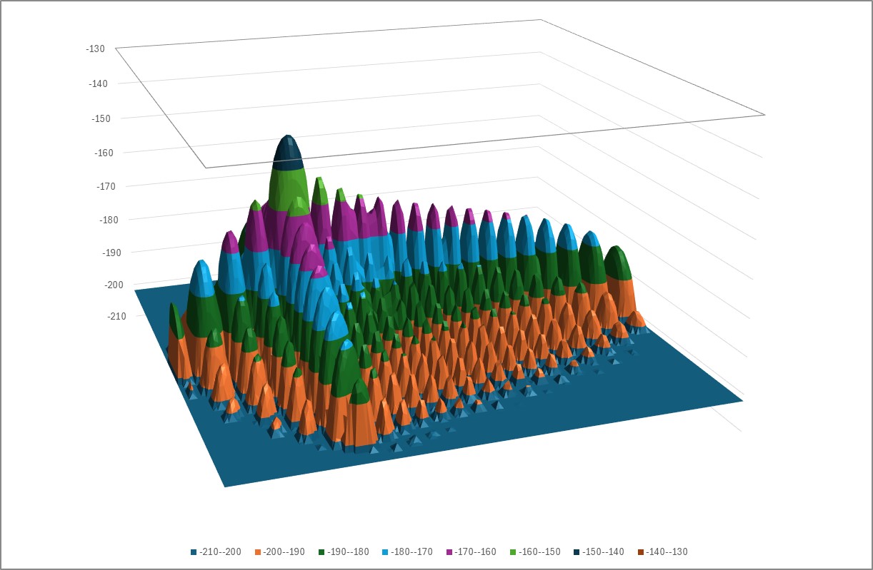
For these scenarios, the PFD Mask Tool has an option to iterate a beam pointing over the field of view of the satellite. For each (az, el) point, the tool identifies if the beam could be active at that location due to the constraints. If the beam could be active, then the peak gain is calculated for that skew angle, and then the power that would be transmitted taking into account the maximum EIRP and whether power control is being used.
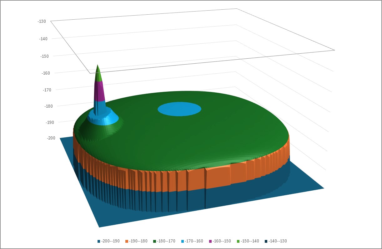
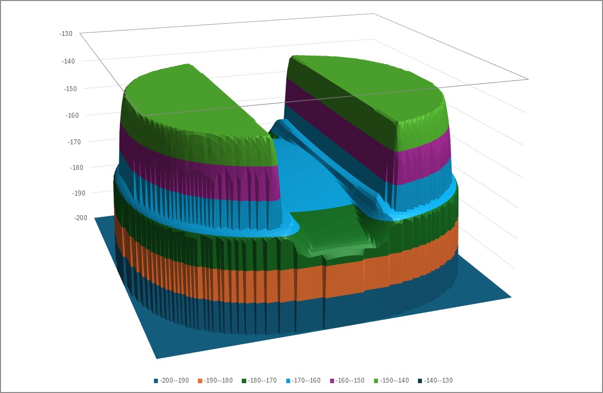
It is then possible to calculate the PFD for all points in the PFD mask assuming the given beam pointing (az, el). By iterating over all beam pointing (az, el) directions, it is possible to derive the maximum PFD at each point in the PFD mask. For example, the figures below show the PFD for a single pointing direction and then iterated over all pointing directions:
As some gain patterns can change rapidly over small changes in pointing direction, in particular for the gain pattern in M.2101, it is possible to use a finer grid when pointing the beam than the resulting PFD mask. This oversampling is typically an integer such as 2 or 4 times the resolution, though note there is a direct impact on run times.
User Interface
The tool is managed via a set of tabs as detailed in the sections below.
Note that software features and the user interface are regularly updated though a continuous process of development.
The user interface can be used to define aspects of the PFD Mask generation process, as described below.
PFD Mask Header
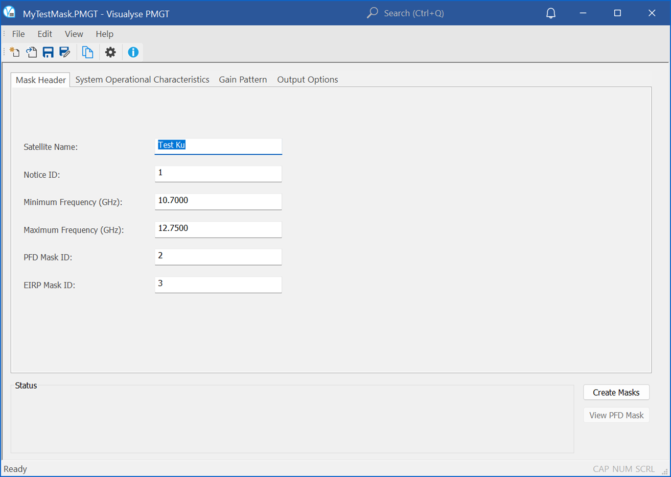
The first tab allows the PFD mask header to be defined, including the:
- Satellite name
- Notice ID
- PFD Mask ID
- EIRP Mask ID (if required)
- Minimum and maximum frequency.
Non-GSO Satellite System
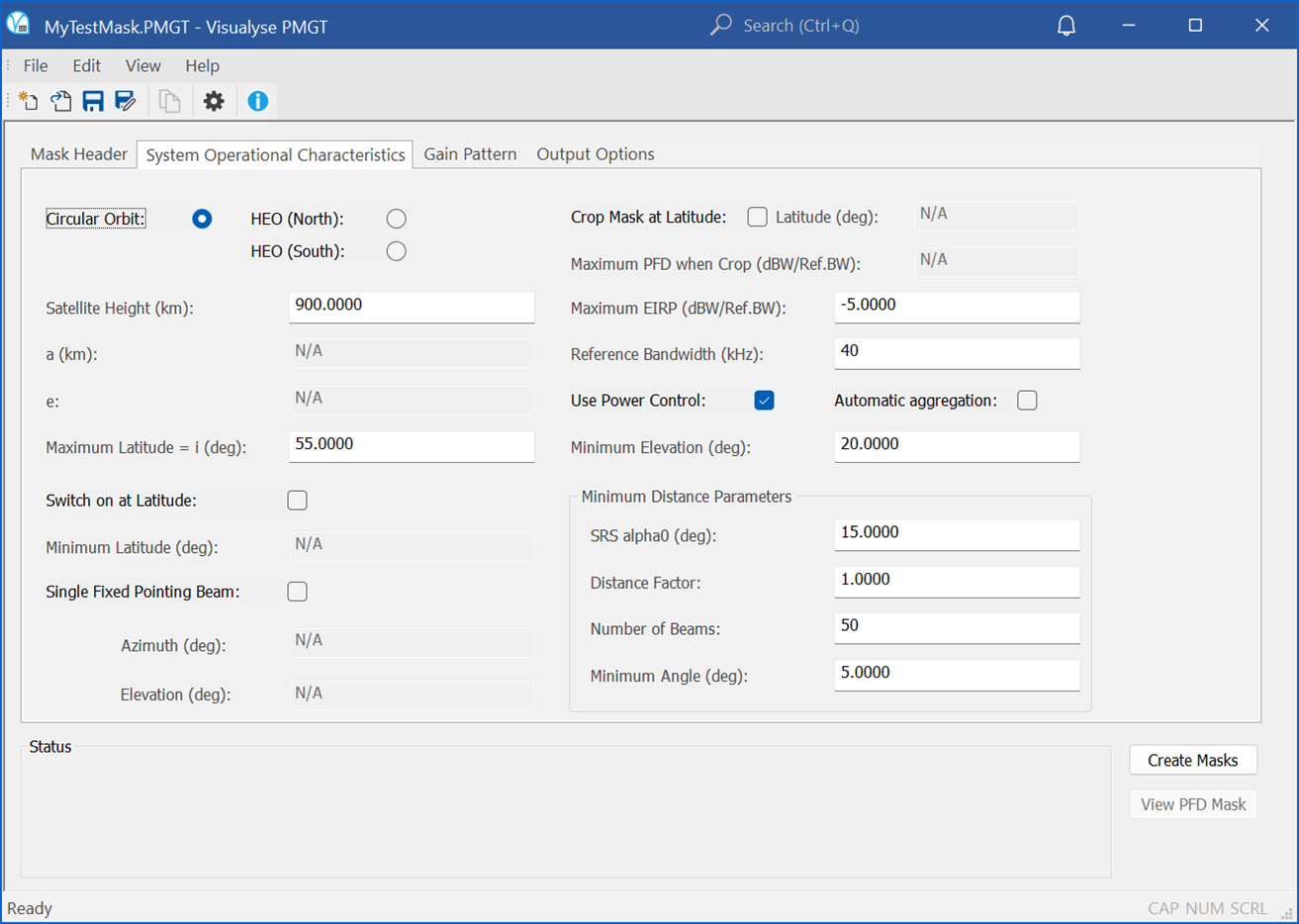
The following tab allows definition of key aspects of the non-GSO satellite system’s design, including:
- Height
- Minimum elevation angle
- Minimum angle to the GSO arc
- Whether the antenna is fixed pointing or steerable
- Whether the system is only switched on for specific latitudes and if so what latitude.
EIRP and Gain Patterns
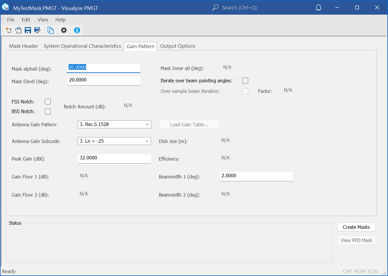
The main section defines the satellite emissions and how the PFD varies. This depends upon whether the antenna is fixed or steerable.
For fixed antenna patterns the key factors are the:
- EIRP
- Gain pattern
- Pointing (azimuth, elevation).
For steerable systems the calculations are more complicated and can include factors such as:
- EIRP
- Whether power control is used
- Antenna roll-off
- Whether additional control is used to manage the in-line geometry PFD
- Whether additional control is used to manage the FSS and BSS gain patterns far-off-axis notch and to remove PFD islands at certain latitudes.
Average Distance
An option allows the average distance to be calculated based upon the parameters entered for the steerable system. A factor can be used to tune this to take account of the likelihood that the satellite used to provide a service will more likely be the one at the highest elevation.
Output
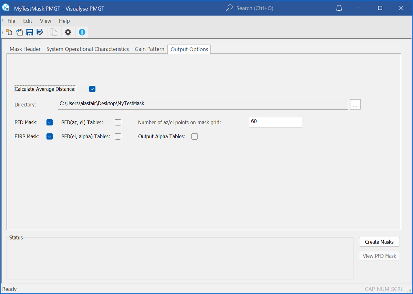
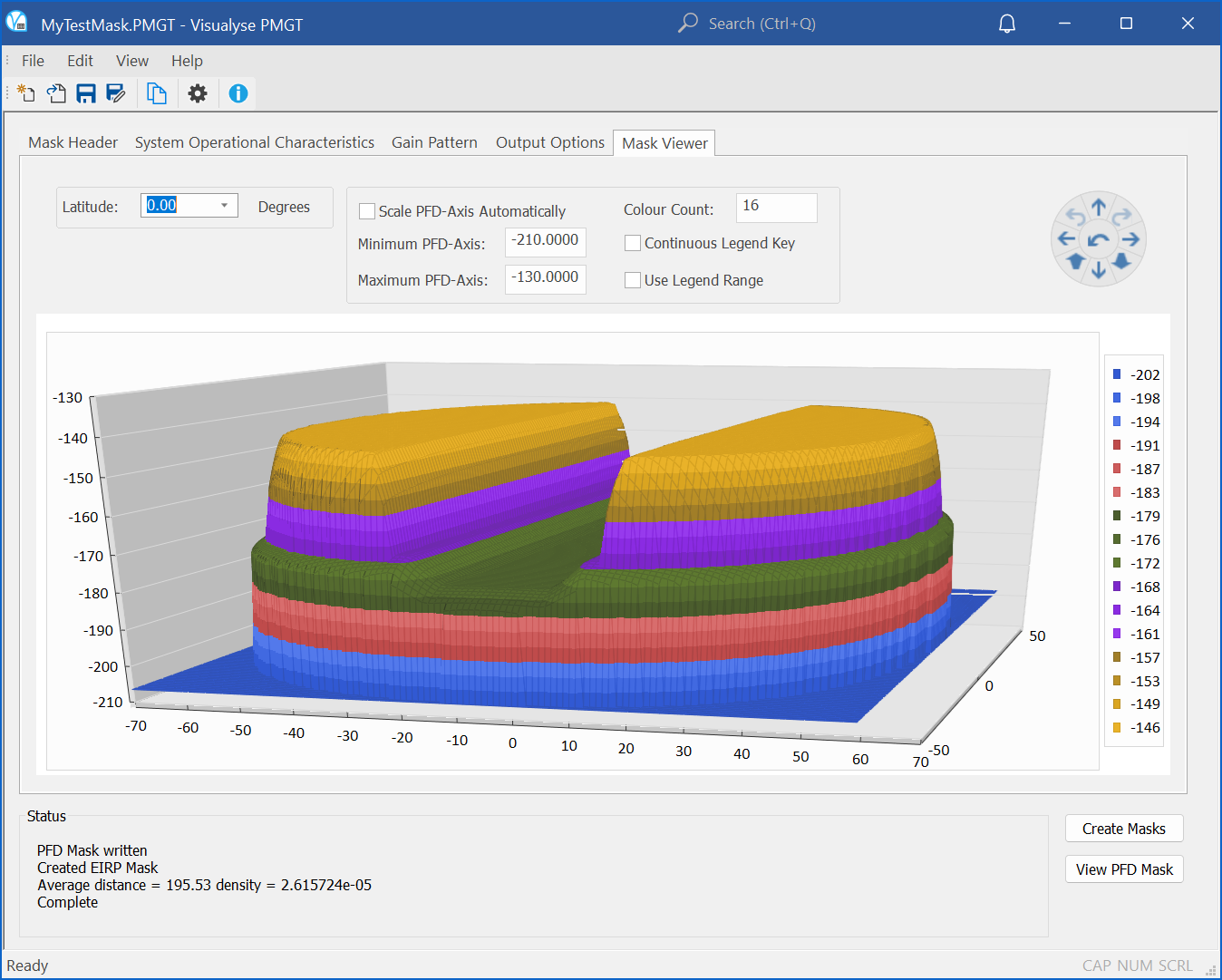
This section defines what should be outputted and what grid to use for the PFD(az, el) format. Options allow additional tables to be created which show slices of the PFD mask at each latitude. It is also possible to use the parameters entered to create a satellite EIRP mask.
A tool is included that can be used to visualise the PFD mask as in the example below:
Version Control
The parameters used can be saved to a text file and used again. This ensures that there is traceability and repeatability of the PFD mask generation process.
Use of PFD Masks in Analysis
Having created the PFD(az, el) or PFD() table at one latitude it would be necessary to repeat the process to create a full PFD mask. This can then be saved in XML format for use within the EPFD verification process.
The result of running the EPFD verification software with a PFD mask is either a pass or fail. This can lead to further questions:
- If the result was pass: which parts of the PFD mask could be increased and by how much?
- If the result was fail: which part of the PFD mask should be decreased and by how much?
These questions can be answered by combining Visualyse PMGT (PFD Mask Generator Tool) with Visualyse EPFD: the latter gives information about how and why the EPFD limits were exceeded while the former allows the PFD mask generation process to be updated accordingly.
An iterative process can be used that results in the highest PFD mask (which therefore provides the maximum flexibility in operation) with a successful pass of the S.1503 EPFD verification process.
Conclusions
This TN has shown how to use the Visualyse PMGT (PFD Mask Generator Tool) to create PFD masks required for S.1503 analysis.